In the previous post, I demonstrated how to download topographic data from free sources for the United States or the world. Now that we have those files downloaded, we need to process them to be ready for our CAD conversion. There are two main options for GIS software: qGIS and ArcGIS. Although either will work for this, qGIS has the advantage of being free and open source. In this post, I will demonstrate how to do the subsetting and conversion in ArcGIS Desktop. The following post will demonstrate the same thing using qGIS.
- Subsetting your raster data:
In most cases, the area you download is going to be much larger than the area you need, so subsetting your data is a good first step.
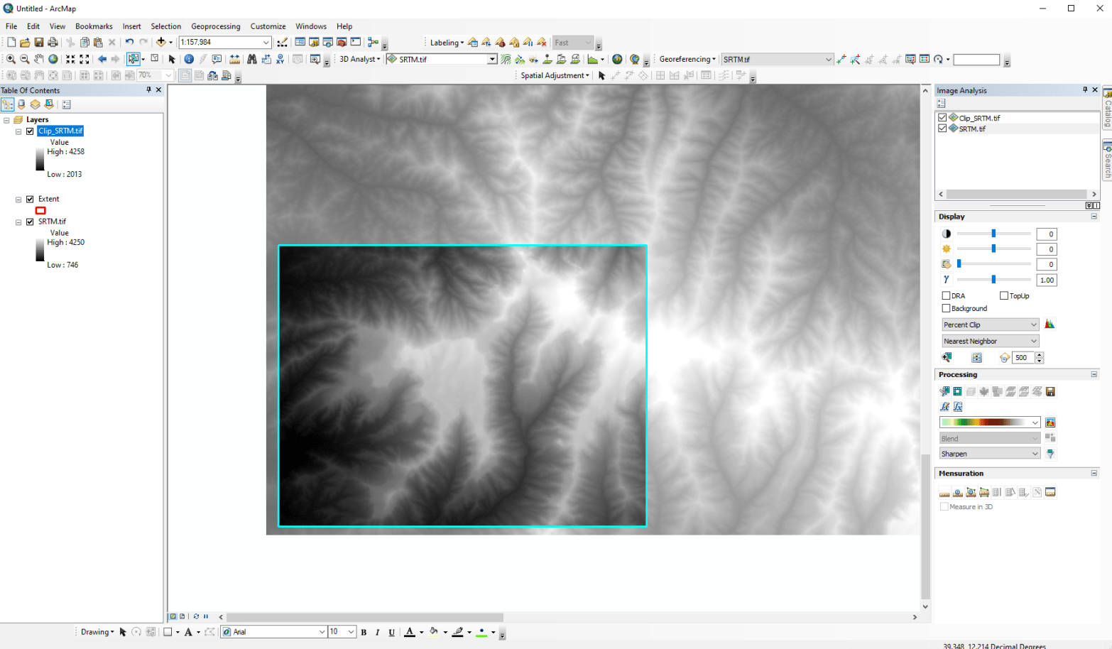
In ArcGIS, you have two options. First, you can use a polygon shapefile to clip it down using the Image Analysis Window (Window -> Image analysis). From there, select the shapefile you want to use, choose the DEM in the Image Analysis window and the click the Clip button (![]() ). This will create a new subset of your DEM.
). This will create a new subset of your DEM.

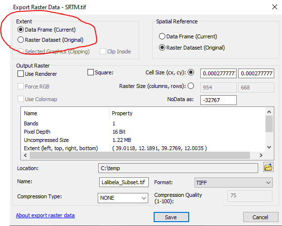
Alternatively, if you need a less precise area, you can zoom to the area you need, right click on your DEM in the Table of Contents and choose Data -> Export Data

This will bring up a new window that you can use to create a copy of a raster dataset. Here you can set the output location and file name and most importantly, change the extent to be Data Frame (Current). This will get rid of the area outside of your current view.
- Creating Contours
One way or another, you should now have a subset you can use to create to contour lines. In ArcGIS, this requires the Spatial Analyst extension. So, if you have not enabled it, you will need to do to Customize -> Extensions and check the box next to Spatial Analyst.
Then, you can search for the tool called Contour. (If you are familiar with the ArcToolbox it is in Spatial Analyst Tools -> Surface -> Contour). The search window should be at the right of your screen, but if it has been closed, you can get to it through Windows -> Search or Control-F. You want the one called Contour (Spatial Analyst)

Once you start the contour tool, you will have a few different settings to fill in. The Input Raster should be your subset DEM, the output is a new file you will store the vector contour lines in. The Contour Interval is how far apart your contour lines will be. Here, my sample area is pretty mountainous, so I have chosen 50 m. You can look at the range of values in your DEM and decide from there.
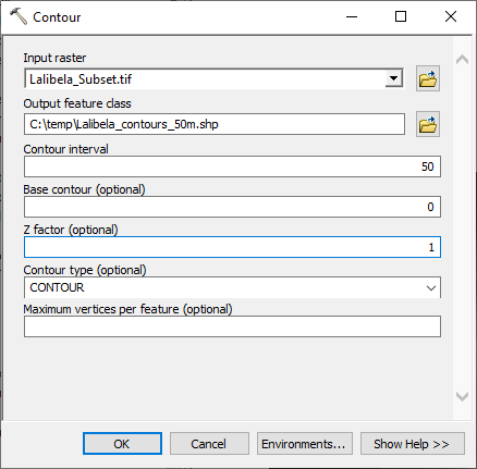
Once it runs, you will have a polyline shapefile (vector data) ready to be converted into a CAD file

- Converting to CAD
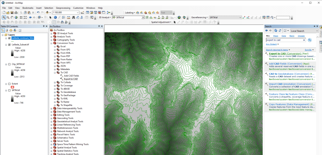
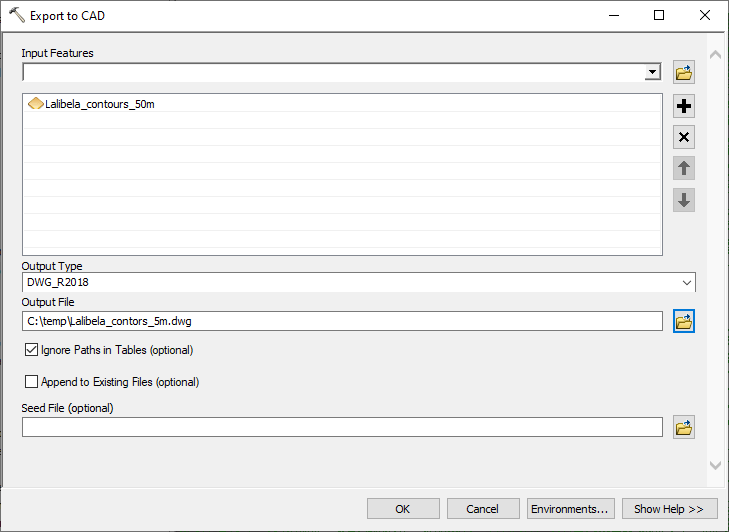
In ArcGIS Desktop, the tool to convert GIS data to CAD is in the ArcToolBox -> Conversion Tools -> to CAD -> Export to CAD. Alternatively, you can also search for the tool called Export to CAD
Once the Export to CAD tool loads, you add in the contour lines you created above, give it an output name and choose some specifics of CAD file structure (I always leave these at the default).
You should now have a contour file ready to be loaded up in a CAD program. In the next post, I will go over the same process in the free qGIS platform.

One thought on “Finding topographic data for CAD projects: Using ArcGIS (2/3)”