In the first of this series, I demonstrated how to download topographic data from free sources for the United States or the world. Now that we have those files downloaded, we need to process them to be ready for our CAD conversion. In the second of this series, I showed how to do the conversion in ArcGIS Desktop. The following post will demonstrate the same thing using qGIS.
Why qGIS?
qGIS has a lot of advantages for this kind of work. First, it is totally free (though donating to the development of free and open source software is a good thing and you should do it!) so you do not need to buy expensive software for a one-off task. Second, it runs on Macs, PCs or Linux-based computers. Third, the whole workflow is just a little easier in qGIS.
- Subsetting your raster data:
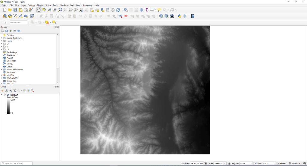
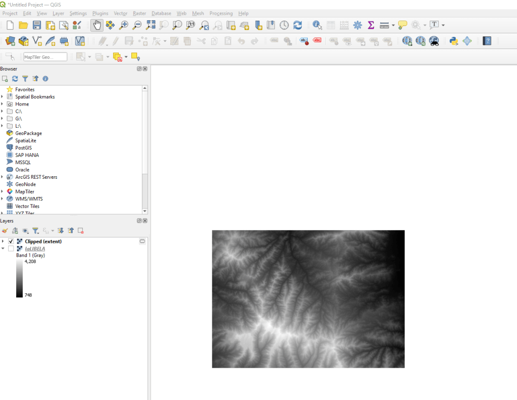
In most cases, the area you download is going to be much larger than the area you need, so subsetting your data is a good first step. To load the file into qGIS, you can just drag it from where you downloaded it onto qGIS.
There are a few options for subseting raster data in qGIS. Most of them are found (at the top of the screen) in Raster -> Extraction
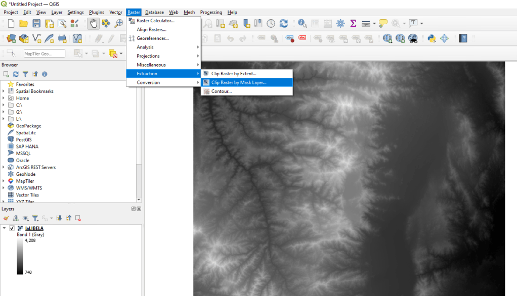
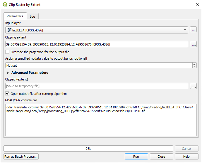
If you have a prexisting shapefile (a vector extent), you can use the Clip Raster by Mask Layer tool to specify an existing file. But most often you will want a specific rectangle defined by coordinates or to specify an area on the map itself. These tools are all in Clip Raster by Extent. Here you will set the Input Layer (your DEM), an output file (can be left as temporary or stored someplace) and set the Clipping Extent. This last one is the 4 coordinates that make up the corners of the new smaller layer you want. If you click on the three little dots at the end of the Clipping Extent box, it will give you the choice to import these coordinates from another layer, the extent of the current view or to Draw on Canvas.

Draw on canvas will let you create a rectangle on your map and use that.

Once this is all set, just choose Run in the Clip Raster by Extent tool
Now you should have a raster DEM that is just the area you need.
- Creating Contours
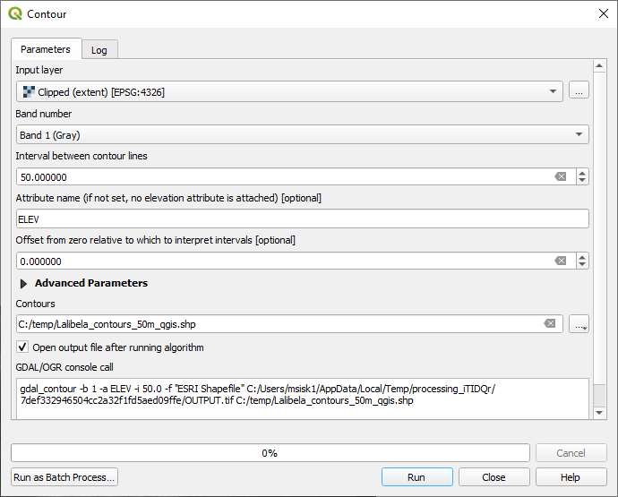
One way or another, you should now have a subset you can use to create to contour lines. In qGIS this tool called Contour. Just like the tools we used before, it is in Raster -> Extraction -> Contour
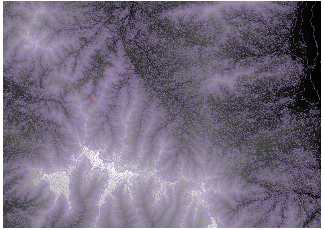
Set the Input Layer to be your subset DEM (if you saved it permanently it will have a different name), the Band number is Band 1. Set the interval between contour lines to whatever you would like. Here mine is 50 meters because this is a mountainous area, yours will likely be smaller. The Output Contours will be set to temporary. This is fine, although below I set it to save in a vector shapefile. Then hit Run.
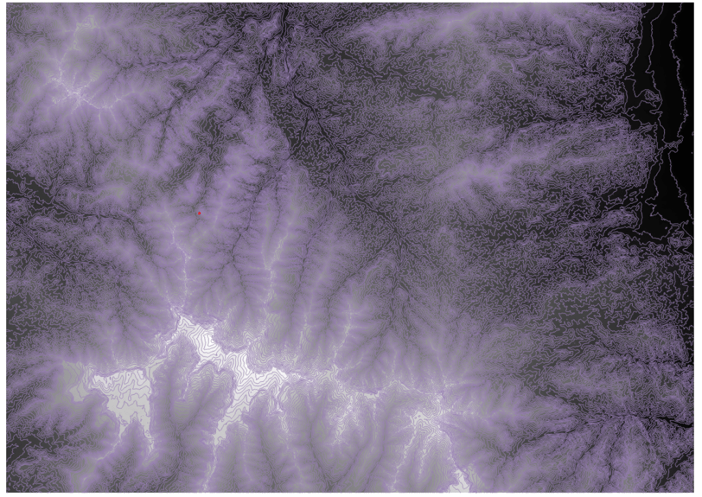
Once it runs, you will have a vector contour data ready to be converted into a CAD file!
- Converting to CAD
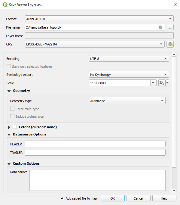
In qGIS , converting a GIS file to CAD is done by exporting the layer. First, go to the layers section and right-click on the new contour lines you created. Then choose Export -> Save Features As

Once this Save Vector Layer As… tool loads, you need to change the Format to AutoCAD DXF and give it an output name.
You should now have a contour file ready to be loaded up in a CAD program!
